
Description
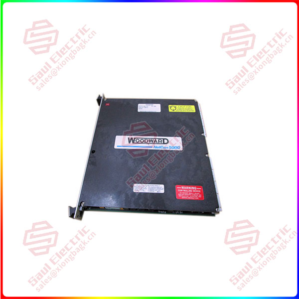
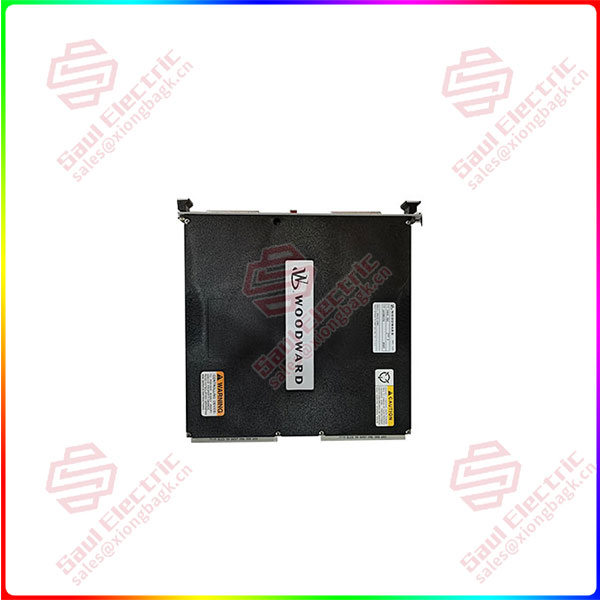
WOODWARD 5464-658 — Digital Servo Drive / Actuator Controller
Product: 5464-658, Digital Servo Drive Module
Manufacturer: Woodward, Inc.
Primary Application: A digital servo controller/amplifier designed to provide precise closed-loop position control for electro-hydraulic actuators (EHAs) and electro-mechanical actuators in demanding applications for gas turbines, steam turbines, and large industrial engines.
1. Core Overview & Positioning
The Woodward 5464-658 is a high-performance digital servo drive module, representing a specific configuration within the 5464 product family. It functions as the critical power and control interface between a primary control system (like a Woodward 723PLUS, NetCon, or other digital governor) and the final actuating device (servo valve). Its primary purpose is to translate a low-level position command into a high-fidelity, high-power output to move an actuator with extreme accuracy and speed.
Key Concept: It forms the innermost loop (position loop) of a cascade control system, ensuring the physical actuator perfectly tracks the dynamic demands of the outer speed or load control loop. This is essential for stable and responsive prime mover control.
2. Key Features & Functions
-
Precision Closed-Loop Control: Implements a high-speed digital control algorithm (typically PID with advanced filters) to maintain actuator position precisely aligned with the commanded setpoint.
-
Dual-Channel Input Processing:
-
Command Input: Accepts an analog position command (e.g., ±10V DC, 4-20mA) from the master controller.
-
Feedback Input: Continuously reads the position signal from an LVDT (Linear Variable Differential Transformer) or RVDT attached to the actuator, forming the feedback for the control loop.
-
-
High-Power Output Stage: Generates a modulated current output (typically in the range of ±150mA to ±300mA) capable of driving the inductive coil of a high-performance servo valve.
-
Advanced Integrated Diagnostics:
-
Continuous monitoring of LVDT health (signal level, frequency, phase).
-
Real-time monitoring of coil current, driver temperature, and output stage health.
-
Detection of excessive position error, command-feedback mismatch, and communication faults.
-
-
Configurable Control & Protection: All operational parameters—including servo loop gains (P, I, D, feedforward), current limits, fault response strategies (e.g., drive to pre-set fail-safe position), and I/O scaling—are configured via software (Woodward Toolkit).
-
Integrated Communication: Features onboard communication interfaces (typically a Woodward proprietary bus like Gov. Bus or a serial link) for seamless integration with the primary controller, real-time data monitoring, and remote configuration.
3. Common Technical Specifications
-
Part Number Context: The
-658suffix specifies the exact hardware revision, firmware version, and possibly default calibration for a particular application (e.g., specific actuator model or turbine type). -
Command Signal: Configurable for standard analog inputs: ±10V DC or 4-20mA.
-
Feedback Signal: Designed for industry-standard AC LVDT/RVDTs, providing excitation (e.g., 3 Vrms @ 2.5 kHz) and measuring the return signal.
-
Output Drive: Current output suitable for driving proportional or servo-proportional valve coils.
-
Power Supply: Requires external, well-regulated DC power rails, commonly ±15V DC for control logic and a higher voltage (e.g., +24V to +80V DC) for the power output stage.
-
Physical Form: A robust printed circuit board assembly designed for mounting in a control cabinet or dedicated drive chassis, featuring high-reliability connectors.
4. System Integration & Configuration
-
Role in Control Hierarchy: Acts as a slave drive unit to a primary Woodward Digital Controller. It executes position commands with high fidelity but relies on the master for the overall control strategy (speed, load, sequencing).
-
Configuration Software: Entirely configured and tuned using Woodward Toolkit PC software. The process involves:
-
Hardware Configuration: Setting I/O types and scaling.
-
LVDT Calibration: A precise procedure to map the LVDT’s electrical output to the actuator’s physical stroke (min/max travel).
-
Servo Tuning: Adjusting the PID and dynamic compensation parameters to achieve optimal step response—fast without overshoot or oscillation—specific to the connected actuator’s mechanical and hydraulic characteristics.
-
-
Calibration Criticality: Accurate mechanical installation and electrical calibration of the LVDT are absolute prerequisites for safe and stable operation.
5. Typical Applications
This module is deployed in applications requiring the highest levels of actuation precision and reliability:
-
Heavy-Duty & Aeroderivative Gas Turbines: Controlling fuel gas control valves (GCVs), liquid fuel metering valves, and inlet guide vanes (IGVs).
-
Steam Turbine Governing: Positioning main stop valves, governor valves, and extraction valves.
-
Large Diesel & Dual-Fuel Engines: Governing actuator control for fuel injection systems.
-
Compressor Anti-Surge Systems: Providing fast, precise control of anti-surge valves.
Reviews
There are no reviews yet.