Description
SST 5136-PFB-104 — PROFIBUS Communication Module
Product: 5136-PFB-104, PROFIBUS Interface Module
Manufacturer: SST (Solid State Technology, Inc.) – now part of Rockwell Automation (acquired and integrated into their product lines)
Primary Application: A PROFIBUS DP (Decentralized Peripherals) interface module designed to act as a slave device, allowing automation equipment (PLCs, drives, I/O) to communicate on a PROFIBUS DP network. It’s commonly used as a bridge or adapter card in systems that need to connect non-PROFIBUS native devices to a PROFIBUS network.
1. Core Overview & Function
The SST 5136-PFB-104 is part of SST’s extensive line of industrial communication interface products. Its primary role is to translate between a device’s internal bus or protocol and the standard PROFIBUS DP fieldbus.
Key Function: It acts as a PROFIBUS DP-V1 Slave, appearing as a standard slave node on the PROFIBUS network. It exchanges data (input and output words) between the PROFIBUS master (e.g., a Siemens S7 PLC, a Rockwell ControlLogix with a master card) and the host device it is plugged into.
2. Key Features & Characteristics
-
PROFIBUS DP-V1 Slave: Supports both cyclic data exchange (for real-time process data) and acyclic services (for parameterization, diagnostics, and alarms).
-
Flexible Integration: Typically designed as a plug-in module or daughter card that fits into a specific host device’s proprietary slot or bus.
-
Dual-Port Memory Interface: Often uses a dual-port RAM interface to facilitate fast, low-level data exchange with the host device’s CPU.
-
Configurable Data Size: The amount of input and output data (the «process image») exchanged over PROFIBUS is configurable via software, typically up to 244 bytes each way, to match the host device’s requirements.
-
Diagnostics: Provides comprehensive diagnostic information accessible via PROFIBUS (slave status, module faults) to the network master.
-
Non-Volatile Memory: Stores configuration (like the PROFIBUS node address and parameters) permanently.

3. Typical Host Systems & Form Factor
The «5136» series modules are device-specific. The 5136-PFB-104 is not a standalone device; it must be installed into a compatible host. Common host platforms include:
-
Drive Controllers: To give a variable frequency drive (VFD) or servo drive a PROFIBUS DP port.
-
Third-Party PLCs or PACs: To allow a non-PROFIBUS controller to connect to a PROFIBUS network as a slave.
-
Specialized I/O or Measurement Devices: To network devices like weigh scales, barcode readers, etc.
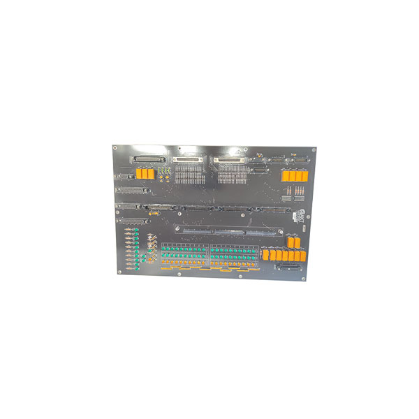
Form Factor: It is usually a small printed circuit board (PCB) with a PROFIBUS connector (9-pin D-sub) and a connector or edge for plugging into the host device’s motherboard.
4. Technical Specifications
-
PROFIBUS Interface:
-
Protocol: PROFIBUS DP-V1 slave.
-
Connector: 9-pin D-sub female (standard).
-
Baud Rate: Auto-detect or configurable from 9.6 kbps to 12 Mbps.
-
Address: Set via rotary switches or software (address range 1-125).
-
-
Host Interface: Proprietary to the host device, but commonly a parallel bus or dual-port RAM interface.
-
Configuration: Requires SST configuration software (e.g., SST PROFIBUS DP Configuration Tool) to set up the data mapping between the host device’s internal registers and the PROFIBUS input/output image.
-
Power: Typically powered directly from the host device (e.g., +5V DC).
-
LED Indicators: Status (RUN/ERR), PROFIBUS network activity (BF), and power.
5. System Integration & Configuration Workflow
-
Physical Installation: The module is plugged into its dedicated slot on the host device (e.g., a drive).
-
Hardware Settings: The PROFIBUS node address is set using DIP switches or rotary switches on the module itself.
-
Software Configuration:
-
Using the SST configuration software, a «Device Description File» (GSD file) for the specific host device (e.g.,
MyDrive_V3.gsd) is imported into the PROFIBUS master’s configuration tool (e.g., Siemens STEP 7, TIA Portal). -
In the master’s software, the module appears as a slave. The user configures the size of the input and output data areas (e.g., 4 bytes in, 4 bytes out).
-
The configuration is downloaded to the PROFIBUS master.
-
-
Data Mapping: Within the host device (e.g., the drive’s own programming software), the user maps internal parameters (speed reference, actual speed, fault codes) to the specific PROFIBUS input/output words defined in the GSD configuration.
6. Common Applications
-
Integrating Non-PROFIBUS Drives: Adding a Rockwell PowerFlex drive to a Siemens PROFIBUS-controlled production line.
-
Legacy System Integration: Connecting older or specialized equipment to a modern PROFIBUS-based DCS or SCADA system.
-
Building Networked I/O Islands: Creating a cluster of devices that communicate via a local backplane, with the SST module acting as the gateway to the wider PROFIBUS network.
Reviews
There are no reviews yet.