Description
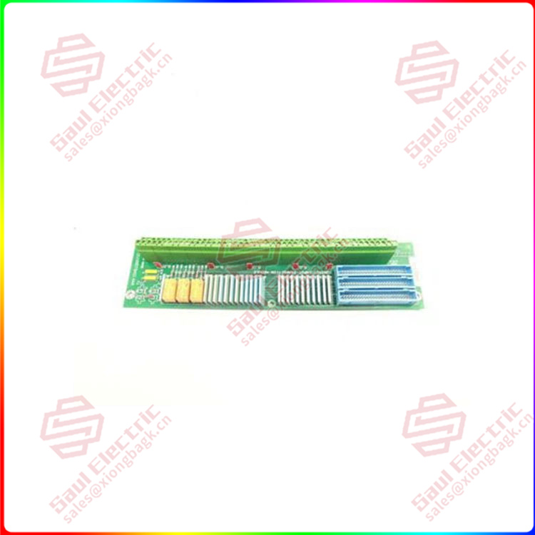
GE DS200QTBAG1A — Terminal Board / I/O Interface Module
Product: DS200QTBAG1A, Terminal Board Assembly
Manufacturer: GE (General Electric), part of the Mark VI / Mark VIe Speedtronic Turbine Control System platform.
Primary Application: A dedicated terminal board (I/O interface module) within the GE Mark VI system designed for the termination, conditioning, and distribution of specific field wiring signals connected to the turbine’s control and protection subsystems.
1. Core Overview & System Context
The DS200QTBAG1A is a specialized interface module in GE’s DS200 series for Mark VI turbine control. Its part number suggests a specific role distinct from other terminal boards (like the TBQ series). The «QTB» core identifier often relates to a quad-redundant or specialized signal grouping in GE’s nomenclature.
Key Function: It acts as a robust, semi-passive junction point between field devices and the system’s active I/O processing cards. Its primary purposes are:
-
To provide a reliable, maintainable connection point for field cabling.
-
To offer basic signal conditioning and protection (fusing, isolation).
-
To organize and route specific groups of signals to their respective processing modules.
2. Key Features & Functions
-
High-Density Termination: Features multiple screw terminal blocks for connecting a defined set of field wires from sensors, switches, and transmitters.
-
Signal Grouping & Routing: Likely designed to handle a specific category of I/O signals (e.g., a group of 16 analog inputs, or a mix of critical digital inputs). It routes these signals via internal printed circuits to one or more standardized connectors that mate with the system’s I/O cards.
-
On-Board Conditioning & Protection: Typically incorporates:
-
Fuses: For overcurrent protection on each channel or channel groups.
-
Resistors: For current limiting or pull-up/pull-down purposes.
-
Isolation/Barrier Components: To provide galvanic isolation between the hazardous field environment and the sensitive control electronics.
-
Surge Suppression Devices: For protection against voltage transients.
-
-
Status Indication: May include LEDs to indicate the presence of field power or to provide a visual fault indication for fused channels.
3. Common Technical Specifications
-
Part Number Breakdown:
-
DS200: Standard prefix for Mark VI system I/O and drive components.
-
QTBA: Indicates the Terminal Board model series. «Q» may denote a specific form factor, connector type, or signal set. This differentiates it from other boards like TBQ, TBC, etc.
-
G1: Generation 1 hardware.
-
A: Final revision or configuration code (e.g., specific fuse ratings, connector vendor).
-
-
Form Factor: A printed circuit board (PCB) assembly designed to be mounted within a Mark VI I/O Pack enclosure (e.g., a TBCI or TBQC frame).
-
Connectors:
-
Field Side: Screw-clamp terminal blocks.
-
System Side: One or more high-density, multi-pin connectors (e.g., AMP, Harting types) that plug into a backplane or directly into a mating I/O processor card.
-
-
Compatibility: Must be used within its designated Mark VI I/O Pack slot and is designed to work with specific associated I/O processor daughter cards (e.g., DS200DIOB, DS200AIOB).
4. System Integration
-
Physical Location: Installed in a slot within a Mark VI Distributed I/O Pack. These packs are strategically located near the turbine auxiliaries to minimize field wiring runs.
-
Role in Data Path: It is the first point of contact for field signals entering the electronic control system:
-
A field device wire lands on the DS200QTBAG1A’s terminal block.
-
The signal is fused/conditioned on the board.
-
The signal travels via the board’s internal traces to its system connector.
-
The connector plugs into an I/O Processor Card, which digitizes the signal.
-
The digitized data is sent via the PDH/UDH network to the central Mark VI Controller.
-
-
Maintenance Advantage: Allows for the replacement of active I/O cards without disturbing the field wiring, which remains securely terminated on this board.
5. Typical Applications
This board interfaces with critical turbine monitoring and control points:
-
Critical Speed & Vibration Probes: Terminating signals from proximity probes or accelerometers.
-
Thermocouple Arrays: Connecting multiple T/Cs from bearings, exhaust, or casing.
-
Analog Process Signals: For 4-20mA transmitters (lube oil pressure, fuel gas pressure, etc.).
-
Digital Status Signals: From solenoid valves, pump motors, or breaker aux contacts.
Reviews
There are no reviews yet.